Relationships
A relationship describes how two entities are connected in the business domain. Configure its direction, storage mode, and cardinality, then manage relationship properties and data when applicable.
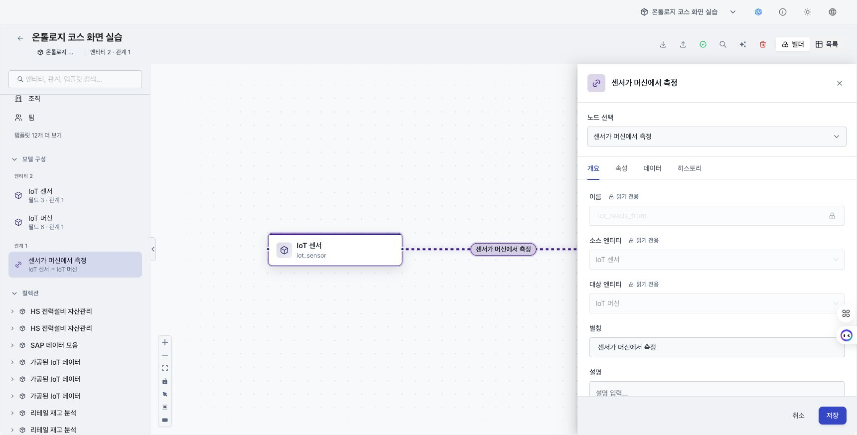
Capture: The create-relationship dialog showing Storage mode, Cardinality, and either foreign-key Reference columns or Component relationships. Use only test model names.
Create a relationship
Create a relationship on the Ontology Builder canvas.
- Drag a connector from the source entity to the target entity.
- The Create relationship dialog opens.
- Enter a name, alias, description, and tags.
- Select a Storage mode and Cardinality.
- Specify the reference columns or component relationships required by the storage mode.
- If you selected a link table, define any required relationship properties.
- Select Create.
Both endpoint entities must have identifier keys before the relationship can be saved. Storage mode cannot be changed after creation.
After properties are added to a link table, you cannot delete or rename an existing property, change its type or nullability, or change the identifier key. To change one of these fields, delete and recreate the relationship. Before deletion, review pipelines that reference it.
Basic information
- Source entity: The entity where the relationship starts.
- Target entity: The entity toward which the relationship points.
- Name: Enter a
lower_snake_casename that begins with a lowercase letter and uses lowercase letters, numbers, and underscores, such asknowsorcontains. Cypher uses this name. - Alias: The representative name shown on screen.
- Description: Record the relationship's purpose and meaning. You can request an AI suggestion.
- Model: The current ontology model that contains the relationship.
Select a storage mode
| Storage mode | Use when | Properties and Data tabs |
|---|---|---|
| Link table | You need dedicated relationship rows or properties on the relationship itself. | Manage the relationship schema and data directly. |
| Foreign-key columns | Existing columns on the source entity contain the target entity's identifier key. | There is no separate relationship table or relationship property schema. |
| Via intermediate entity | You want to display a derived relationship by joining two existing relationships. | Data remains on the intermediate entity and component relationships; there is no separate Data tab. |
Link table
This is the default storage mode. It supports N:N, N:1, 1:N, and 1:1 cardinality and can store relationship properties.
Foreign-key columns
Select Reference columns on the source entity that correspond to the target entity's identifier key. Only nullable source columns with the same data type as each target key are available.
A foreign-key relationship supports only N:1 or 1:1, because one source row points to one target. When the relationship is created, existing column values populate graph connections. Review these states on the relationship detail page.
- Populating graph: Connections are being created from existing rows.
- Graph load failed: The relationship and source data remain, but graph updates are behind. Select Retry to run the load again.
Via intermediate entity
Select a First relationship and Second relationship. The first relationship's target and the second relationship's source must be the same intermediate entity. The complete path must start and end at the new relationship's source and target.
Cardinality is derived from the two component relationships and cannot be changed directly. On the canvas, use Collapse intermediate to hide the intermediate entity and components and view the derived relationship as one hop.
Set cardinality
| Value | Meaning |
|---|---|
| Many-to-many (N:N) | Source and target instances can each connect to multiple instances on the other side. |
| Many-to-one (N:1) | Each source instance can connect to one target instance. |
| One-to-many (1:N) | Each target instance can connect to one source instance. |
| One-to-one (1:1) | Each instance on either side can connect to one instance on the other side. |
You can edit a link-table relationship's cardinality after creation. When saving a stricter constraint, D.Hub first checks existing rows for violations. If there are no violations, it applies the constraint. Otherwise, the Cannot tighten cardinality dialog shows duplicate keys and related row counts.
Choosing which connection to retain requires a business decision, so D.Hub does not delete duplicate rows. Clean up the relationship data and save the cardinality change again.
Schema — identifier key and display column
A link-table relationship can have schema information like an entity.
- Identifier key: If the relationship has a schema, select key columns that distinguish its rows. A link-table relationship can exist without properties or an identifier key. The pipeline editor can show a key warning on a relationship node, so review the target schema and execution result before using it as input or output.
- Display column: The property shown as the representative name for each relationship.
Load data
On a link-table relationship's Data tab, upload a CSV, JSON, or Parquet file, or connect code output to the relationship in a pipeline. Pipeline fields are not mapped automatically, so make the output column names and types match the relationship schema.
For a foreign-key relationship, change the source entity's reference columns. A relationship via an intermediate entity uses the data from its two component relationships.
Data tab
Review relationship data page by page. Columns appear in identifier-key, display-column, and remaining-property order. Refresh, upload, download, open in Graph Explorer, and initialize the table. See View rows on the entity Data tab for the initialization confirmation procedure.
Edit or delete a relationship
- Select an edge on the canvas to open its details in the right panel.
- Edit the alias, description, tags, and cardinality for a link-table relationship. The name, source and target entities, and storage mode are read only.
- Select the edge and press
Deleteto delete the relationship.
To define several relationships, use AI relationship suggestions to analyze the current model and create only selected source-relationship-target proposals. To remove all entity and relationship types from a model, review the target and progress under Reset ontology data.